| < Return to index page |
Modelling Oil Refineries and Storage and Distribution Depots
Oil has been imported in bulk since the 1880's but up to the 1920's most internal movement was still in wooden barrels. Tank wagons rectangular bodies and (as per the Graham Farish model) and those with tubular barrels (resembling the Peco ten foot wheelbase model) appeared on the railways in the 1880's but there were few routes with facilities to handle bulk liquids at both ends. Horse drawn road tank wagons appeared at about the same time but these do not seem to have been very common. By 1920 the horse drawn and motor road tanks were often elliptical in section rather than rectangular or cylindrical. In the later 1920's oil tank railway wagons began to appear in greater numbers as recipients developed rail links and installed bulk storage tanks and by the mid 1930's the wooden barrels had largely been displaced.
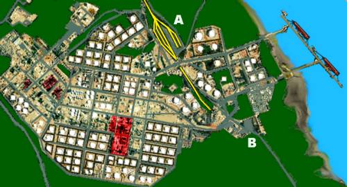
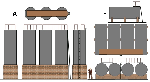
You have to see a refinery from the air to grasp the scale of the establishment, the site will typically occupy roughly 400 acres. The sketch below shows a typical arrangement for a British based refinery on a river estuary. The railway element (tinted yellow) marked A is located on the edge of the refinery proper, in this case between the refinery and the jetties where the ships arrive (this is not uncommon, Coryton is similar). The road lorry loading depot marked B is also on the very periphery of the refinery. Both are some distance from the tall towers and other distinctive structures (in the areas tinted red).
Fig : Plan view of a typical refinery complex
Note the arrival, departure and run-round loops are separated from the loading sidings, railway company locomotives will drop off and collect from the loops, they are not allowed into the loading area.
The loading area will usually feature several quite long sidings to accommodate the rolling stock, an ideal minimum from the later 1960s to date would be two sidings each two feet long. That would allow a train of eight bogie 100 tonners to be handled, which looks acceptable. Cutting the sidings down to eighteen inches allows a train of six modern bogie tankers (or twelve 45 tonners), which is really an absolute minimum. For pre-war and immediate post-war (green diesel era) layouts, running the older and smaller tanks, eighteen inch sidings would be fine and you could get away with fifteen inches length.
The loop(s) must be long enough to handle the longest train, assuming they dead-end you also need a loco release headshunt. In the prototype example shown above this is very long, allowing it to be used for shunting as well, this is a feature of several refinery loop yards in the UK. An ideal minimum is two loop lines (arrivals and departures), each four feet long, and a release road. If space is very tight you can get away with shorter loops if you leave some wagons on the approach line, run round the first cut and collect the second cut for the second siding.
As well as the products being shipped out there will be some materials being supplied to the plant such as the chemicals for processing the oil. These are not delivered to the loading area but have their own siding(s). Bitumen is also usually handled at a separate set of sidings from the petrol, fuel oil and lubricants.
In the loading sidings there has to be access to the tank tops, up to the 1970s this was always open raised walk-ways with simple 'cranes' from which the loading hoses were suspended. The rake of wagons would be shunted into position by a works loco, men would open the tank lids, insert the pipes and all the tankers would be loaded more or less simultaneously. The structure was very like the 'top discharge' arrangements required for Class A liquids up to the 1960s. The example shown is for a discharge point, for a loading terminal the structure and cranes were similar but there were rather more pipes running along under the walk-ways.
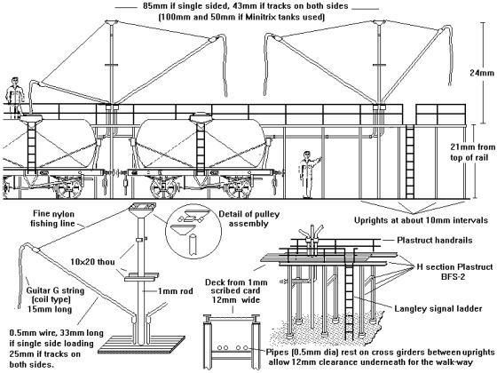
Fig : Petrol cranes
More recently a number of terminals have installed a single loading point with a cable-hauled system to move the wagons through, each being loaded in turn. These one-at-a-time loading points are either a large girder structure enclosing the track, or an elevated building.
Loading points have a number of pipes, each delivering a different grade. These pipes would be painted either light grey or black, and in there somewhere would be a red water line to feed the fire fighting 'monitors' (which look a bit like small anti-aircraft guns and are painted red). I remember seeing a pipeline painted white as well, although I have no idea what that was for.
Where a permanent walk-way was not justified (that is where only occasional wagons were loaded, such as at a bitumen loading point, a light frame mounted on small wheels would be provided. This frame carried a swinging arm or gallows arranged to be higher than the rail tanker top hatch, and from this would trail the black rubber two inch discharge hose. These were regularly used for loading bitumen wagons at the refineries into the 1970's and possibly the 1980's. This was cheaper than building a fixed gantry, the frame could be moved along the siding to where it was needed (see under Bitumen below).
From the above we can start looking at how a refinery might be incorporated onto a layout and as so often with industrial modelling a corner location offers the most scope in this area. The example shown is not prototypical in several ways but represents the smallest space option. For a start we can pair down the facilities, two sidings for tankers, one siding each for bitumen and refinery supplies and a single loop using the main line as a run round. Not prototypical but this is about as small as it can get. LPG is assumed to be handled at the main loading area but the facilities at C could be used (for model purposes) if the sidings were occupied. The track plan uses double slips on the loop line to save space but even so the upper section would extend some three feet six inches (about 1m 15cm) from the corner, with the lower section extending some two feet six inches (75cm) from the corner, and that is an absolute minimum. The railway is effectively passing through the refinery and there are strict rules about running pipes under or over a railway. In the UK there are places where a line passes between two sections of a refinery 'area' although I am not sure it is all one refinery, so this is borderline legitimate.
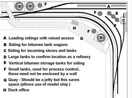
Fig : Refinery in a corner
The sketch is not to scale, you could probably get a few more storage tanks into the scene. The bitumen and stores sidings are usually taken off the loops (in at least three refineries I know of this is, or was, the case) and they usually run in the same direction as the petrol and fuel oil loading sidings, so a shunter is always at the same end of the rake when working the loading sidings. This was not possible in such a confined space so on the plan the bitumen and stores lines run from the far end of the loop, however as this layout does not anticipate the use of a shunter this is not a problem.
No pipework is shown on the plan but there should be rather a lot. Note that pipework in a refinery is almost always raised, typically to chest height where it runs beside a roadway but in crowded areas there is room to walk underneath. Raised pipes allow spills and leaks to be quickly spotted and metal trays can be placed under them until a repair can be effected.
There should also be pipework connecting the jetty to the refinery however that would pass over or under the 'main line' which is problematic. The plus side is that the road and over bridge are within the refinery limits, so this need only be one vehicle wide as it serves only as access to the jetty. On the model the bridge provides a scenic break between the refinery and the rest of the layout.
This suggestion really precludes the use of an industrial shunter, unless the headshunt on the loading sidings end were extended to the left by one sidings length. To allow a railway company loco to shunt the sidings without entering them a long wheelbase wagon would be left on one of the sidings. These were known as a 'reach wagon' and a Peco plate wagon or tube wagon would serve for this duty.
Given more space you can add some suggestion of the refinery proper, there are a lot of small tanks and small buildings associated with the various processes but I believe most people would wish at least a representation of the tall towers. What these look like depends on the period modelled, pre war they were encased in a scaffolding of girder work, by the 1950s there would be some kind of framework extending up at least one side, nearly to the top, with more toward the base of the structure. Pre-war everything was generally much darker than modern plant, I have only found black and white illustrations but I would suggest medium grey for the central tower and very dark grey, almost black, for the platforms and steelwork. The paints available that could handle heat and adhere to metal were limited, which is why there was comparatively little variation in railway engine colours. Industrial plant (as with goods railway engines) favoured black, but for modelling purposes dark grey looks more realistic. In the illustration below note how the pipework is elevated to above head height, you can see the roof of a small building near the bottom that gives some idea of the scale.
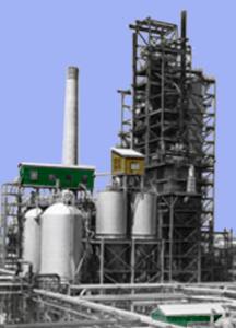
Fig : Large structure at a 1940s oil refinery
By the early 21st century the fractionating towers were virtually free standing and did not have the girder work around them. The pictures you see of modern plant usually show new installations, in use the shiny silver is often reduced to dull shades of grey and often to a dull brown (this colour seems common in areas processing lube oils) and a few are very dark grey. Similarly the storage tanks are mainly white (paint, they are made of metal not concrete) but you do get quite a few dull grey ones in process control areas and a few (presumably handling hot liquids are rust-stained.
The image below was found on Wikipedia (http://www.wikipedia.org) and a hi-res version is available on that site if you search for 'fractionating towers'. To give some idea of the scale of the things the 'man rings' on the ladders are about 3 ft or 1m apart. You can reduce the overall height quite a lot and still keep the look of the thing as they are usually seen from below (in the same way that very short model train points look okay because the real thing is seen at a shallow angle).
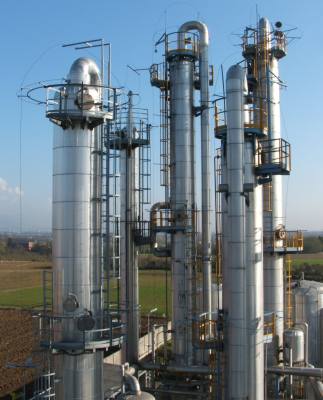
Fig : Photo of fractionating columns
At the base of the tower you need a horizontal run of pipes about a foot in diameter (I think they are lagged) leading to a row of small tanks close by the base of the tower and usually raised above head height. The Ratio oil tanks would do for these, you should have at least eight of them, ten would look better. There is then a lot of pipework connecting the tower and tanks to the rest of the refinery.
As noted above you would expect to see two such towers, and close by (often between them) will be a building with a very tall chimney (I have no idea what the chimney was for but they all seemed to have one).
There are now commercial models of oil refinery structures including some tall towers on the model railway market, however if you are broke they are not too difficult to make. Start with a suitable tube, you can use a cut-down ping pong ball for the top (cut in half, glue to the tube, trim with scissors, finish the trim with toenail clippers). The pipework on the sides are various thicknesses of wire and a straw can be used for the big gas pipe coming down from the top, modern straws have a handy 'bendy' bit that looks well on a refinery. Man holes in the sides of the towers are disks of plastic cut with a paper hole punch and bedded onto a blob of Milliput, The ladders are from signal laddering, man loops can be cut from drinking straws (although gluing these can be tricky, test a sample before doing a lot of work). Hand rails can be added using etched signal laddering (O gauge can be used as-is, OO gauge needs supports) or Slaters brass wire (rose wire and most other wires are not stiff enough to survive).
Some years ago I made a small tower (for a chemical plant) using a Vicks Inhaler (available from your local chemist) which has a nice dome ended cover. I just added a second section to make it taller and some pipework, a couple of platforms and some ladders. The tower was silver stained with black and shades of brown, the platforms walkways slate grey and the platform edging, ladders and handrails were painted white.
Another feature of a refinery (as opposed to a storage depot) would be a few tall chimneys. The process produces a series of unpleasant gasses which are passed up the chimney and often 'flared' (deliberately set on fire) at the top. The chimneys should be at least six inches tall in N and will not be the standard brick affairs associated with mills but are more likely to be silver metal with an external framework (these often have multiple pipes running up them) or a concrete tube with perhaps three metal pipes sticking out at the top.
The metal type can be made using any suitable tubing, the framework can be represented using microstrip with angled side supports from three or four Heljan 'lighting masts', suitably sanded down to give a thinner look. The side supports should extend a minimum of about two thirds of the way up the tube.
The concrete type is typically eight foot (2.5m) in diameter and white but usually the top twenty foot or so is painted black, as are the pipes sticking out of the top. The chimneys used are usually straight sided with no taper, you could use Plastruct tubing but pens with a suitably shaped body about ten to fifteen millimetres in diameter would do just as well if you can find one long enough.
Early oil storage tanks were (typically) 90 feet (30m) in diameter and 30 feet (10m) tall, they had a low conical top (usually I believe wood covered with metal plates). By the later 1930s domed tops made of welded steel were widely seen and these had replaced the older conical topped tanks by the 1960s. A lot of tanks in a modern refinery have a 'floating roof', the tank top floats on the contents, eliminating vapour-space in the tank. These are not as far as I am aware commercially available but for more on these see 'Lineside Industries - Prototype industrial ancillary structures'. On an N Gauge layout a tank farm of several seven inch (18cm) diameter tanks requires a prodigious amount of room, however you can get down to tanks of only four inches (100mm) diameter and just under two inches (50mm) in height and they still (just about) look big enough to be acceptable.
Storage tanks in a refinery are always surrounded by a low wall or earth embankment, perhaps five foot high, to act as a containment should the tank leak, technically termed a 'bund wall' the enclosed space has to be sufficient to contain a completely drained tank full, which in practice means as much space around the tank as is contained in the upper part of the tank (above the height of the wall). The pipes emerging from the tank pass over the top of this wall or bank, they do not as a rule pass through it.
There are several kits of storage tanks for both liquids and gasses available. Kibri offer what I believe is the best storage tank (B-7466 is in Esso livery, B-7462 is in Aral livery), consisting of a pair of tanks complete with a low surrounding wall and a set of pipework and control valves feeding into 'buried pipes'. Also from Kibri is a set of four small horizontal tanks and a small vertical tank ((B-7456). Faller offer a spherical tank of the kind used for holding pressurised gasses (kit number 2130) and they also offer a pair of rather small tanks, however I would suggest replacing the rather heavy handrails on the latter with Plastruct Fineline mouldings. The tops from aerosol canisters can be used to good effect to represent smaller storage tanks. Roads in the refinery area are also commonly raised on an earth bank so they will not be covered by a spill.
Refineries also make use of the tall cylindrical tanks, similar to the 'boiler' tanks used in coal tar works (see Lineside Industries - Coal Tar and Wood Tar Distillers for a drawing), although those I have seen (since the later 1970s) have all been rather clean steel or clad in concrete. These were presumably used to handle bitumen and similar very viscous liquids, hence they would heated to allow the product to flow and would be seen close to sidings dealing with bitumen tank wagons.
Also produced at the refineries are the Liquid Petroleum Gasses (LPG), such as Butane, Propane and Ammonia. These are liquefied (usually by refrigeration) and mainly stored in spherical tanks (see Lineside Industries - Prototype industrial ancillary structures) before being shipped out in pressurised tank wagons. The BP refinery at Llandarcy (opened in 1928 and the UK's first crude oil refinery) was only source of marketable propane until well after World War Two, production began there in 1936, stopped during the war, and was resumed in 1951. Propane production at BP's Grangemouth refinery only started late in 1955.
Rail tanker LPG traffic only started in the later 1960's, prior to that date limited quantities were shipped in smaller pressure canisters and cylinders in standard railway wagons (although chlorine was shipped by rail pre-war).
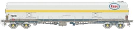
Fig : Esso gas tanker from a 1960s BR advert
Distribution Centres and goods-yard retailers
From the refinery the oil and gas is shipped mainly to distribution depots, either by rail or pipeline within the UK. From the distribution centre it is delivered by rail or road (occasionally barge) to the customers, either larger industrial users or local retailers.
A discharge point at a distribution terminal could form part of a layout with most of the terminal itself painted on the back-scene. A typical installation has a single line passing through a gated entry into a fenced area, they might be three or four sidings, each long enough to handle perhaps ten of the 100 ton bogie tankers (or the equivalent length of other types).
It has long been standard practice to have a fairly long wheelbase wagon on hand, known as a 'reach wagon' which can be coupled between the loco and the rail tanker wagons so that the loco does not have to get too far into a dangerous installation when shunting tanks. Old plate wagons (the Peco long wheelbase 'plate' wagon) are often used as 'reach' wagons, kept at the terminal these often have their sides removed and laid on the floor. In the early 1980's redundant ferry wagons similar to the Peco long wheelbase 'tarpaulin' wagons were also used as reach wagons. If a long wagon was not available a pair of standard five plank open wagons was used, a single ten foot wheelbase wagon would not be long enough.
One point to remember is that bottom discharge of Class A (very flammable) liquids such as petrol was banned at the turn of the century, following leaks onto the track. Class A tankers were loaded and discharged through the top using hoses and at even a small terminal there would be a raised walk-way to give access to the tank tops. This would be equipped with swinging arms from which dangled the black rubber loading or discharge pipes for the wagons.
Fig : Petrol cranes
This requirement for top discharge of Class A liquids was dispensed with the 1960's but some of the terminals equipped for this kind of handling remained operational at least into the later 1970's as the older top-discharge wagons remained in service.
A simple storage or distribution depot is an attractive option for a layout, it might be located anywhere in the country and would consist of tanks and rail and possibly road tanker facilities. The storage tanks might be some distance from the loading/unloading point and this would not be on a siding close to the main line where sparks from steam loco's would be a hazard. A spur to an oil or petrol terminal can therefore be used to fill in an awkward corner of a layout. There are kits of oil storage tanks available in Continental ranges if you have room for them but they can be assumed to be some distance away.
A modern oil depot can be a very compact affair, these days the top discharge for Class A liquids is no longer required, flexible hoses leading to simple hydrant type connections are used. Generally at larger terminals there are two tracks, one to each side of the hydrants, however smaller terminals can have only a single track.
The hydrants feed into pipes which are sometimes buried under the ground, in which case the pipework usually comes to the surface close by and thereafter most pipes are above ground, supported on simple steel bench work and usually a light grey colour. At many installations there is a single large (6-10 inch (15-25cm) diameter) pipe running alongside the siding. The flexible hoses are dark grey (silver for LPG) and about four inches (10cm) diameter with a light grey coupling on the ends, the hoses are normally left attached to the valves and at modern installations there is sometimes a hooped support to carry the hose when not in use. The example illustrated below is typical, the hydrant at the front has a problem, hence no hose and a red warning label attached to it. The track is laid on bare concrete and sits in a shallow trench to contain any spillage, the hydrant and pipe are on a raised concrete platform and the area to the right is gravel.
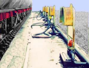
Fig : Fuel oil terminal
Coloured bands are sometimes seen on pipes, to help the terminal workers to trace out the line. Loading valves are often painted black, red or green but the oil products break up most paints so near the hydrant connections the paint gets patchy with black areas showing through. The loading or unloading area would have a raised bank of earth round it and the gate into the area might have a rubber seal along the bottom.
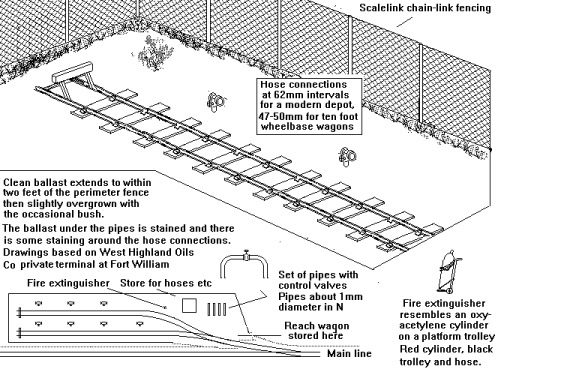
Fig : Class B oil loading/discharging
One standard feature of any oil or gas handling installation since the 1960's would be fire monitors (a small depot might have only one). These are metal 'cannon' like objects that squirt out foam in case of a fire, they are always painted red. They can be fixed or mounted on a mobile trolley, for modelling purposes the fixed type are much easier to make.
In addition where volatile chemicals are involved (LPG, Ammonia and the like) there are usually 'Spray Rails' mounted above the tracks, these are two inch diameter pipes fitted with spray nozzles on the under side. In the event of a fire these generate a water mist over the rake of wagons, which is the best way to prevent the fire spreading and also stops the heat of the flames reaching nearby tanks etc. Normally there are two rails above each track, so that each side of every wagon will be covered, they are supported about every ten to fifteen feet by a light metal arm. Often there are two sets of arms, each one supporting one of the spray rails.
Not all depots were so complicated however, oil fired central heating appeared in the 1930's and was popular from the 1940's until the big oil price rises in the 1970's. Heating oils are Class B liquids, which do not require the top loading/discharging arrangement. Coal merchants often had a yard adjoining the railway goods yard at the local station and these firms often branched out into supplying domestic heating oil. These yard based facilities are discussed in the section on Railway Company Goods Facilities - Coal and Heating Oil. The tankswould be quite large, in N a 'till roll' with plastic card ends would serve fora horizontal tank. Add anaccess hatch from a disc of 40 thou card at one end and a bit of wire bent overat the top as a 'breather pipe' at the other. Alternatively the tank body from an American oil tank wagon can be used. It would be normal to enclose thetank in a brick wall so that if it leaked the spill would be contained. Inaddition there will be a small building housing the pump (used to transfer theoil from the rail tanks to the storage tanks and also to load deliverylorries).
Larger heating oil terminals had large storage tanks but often had smaller tanks acting as buffer stored for loading the lorries. The sketch below assumes you have used the tops from aerosol cans for the storage tanks and Ratio oil tanks for the buffer stores (raised on tall brick supporting walls so they drain into the lorries by gravity). The loading point consists of cranes supported on the H section girders supporting the corrugated iron pitched roof. The general arrangement is very loosely based on a rather larger heating oil terminal operated in the 1960's by Charringtons, a major London fuel merchant. The layout as shown is about the minimum for such a depot, the prototype had two rail tracks, several large storage tanks, a number of lorry loading points each with a smaller buffer tank or two close by and several odd buildings including a canteen or mess for the lorry crews and terminal staff.
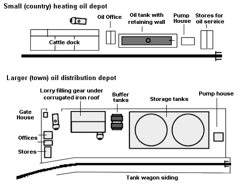
Fig : Rail Connected Heating Oil Merchants
The merchant might well have a tie-in with an oil company, meaning the lorry would be in the oil company colours, typically with the merchant's name and details on the cab doors. The examples illustrated below are (left) a 1937 Albion and (right) a Cory Bros lorry (the distributors for Shell-BP heating oils in London during the 1960s).
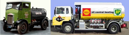
Fig : 1960s Fuel Oil Distributors Lorry
A further variation is a tank farm operated by an oil importer, of which there were quite a few dotted around the coastline, mainly in industrial centres such as London, Manchester and the North East. One such establishment was set up in the early 1880s had a series of large circular iron tanks, some capable of holding 3,000 barrels of petrol. Many of the tanks were situated 15ft below ground level in a special 'oil pit', and the majority of the wharf was itself below the level of the river. This establishment was taken over by the London Oil Storage Company in 1885 and in 1913 the site was described as comprising 'a two-storey brick office building and dwelling house, a brick coopers' shop and a corrugated-iron store in a group at the entrance; two brick warehouses for storage and filling, a pump and filling house, engine house and boiler house, a carpenters' shop, blacksmiths' shop, store, and cloakroom and a total of 27 oil-storage tanks with a combined capacity of over 14,000 tons, including two giant tanks named 'Reliance' and 'Excellent' with individual capacities of 3,000 and 4,000 tons respectively.' I believe they had a railway siding from the London docks for dispatching the imported oils inland. Such a facility can be modelled against the backscene and need not take up as much room as might be thought.
The tanks at a larger inland depot do not need to be modelled unless you have the room, they were often be buried in the ground close by but small tanks from the various kit manufacturers would serve and simple tanks made from snap-on aerosol canister caps would do.
Liquefied Petroleum Gas (LPG) and Liquid Natural Gas (LNG)
LPG's include propane, butane and various more exotic gasses. The first two are routinely used for heating but propane cannot be used indoors as the products of combustion are poisonous. One slight problem is that butane is a liquid at below about -5 degrees Celsius, so it is no use as a fuel in cold climates. LPG was produced in Britain by the Riverside Oil Co around the turn of the century although there was little interest in it at the time. In America however things moved rather more quickly and by the time of the First World War the Americans were using butane for domestic heating and cooking. The idea was taken up by the French and in about 1935 the Modern Gas and Equipment Company was set up in Britain to sell imported French 'Calor Gas'. This became the Calor (Distributing) Co. Ltd., a British registered company (for many years this was owned by the Imperial Continental Gas Association, set up in 1824, Calor Gas was sold to the SHV Gas Group, a private Dutch company, in 1984).
Customs officers felt that butane was a rather dangerous material to be shipped across the channel so supplies were purchased from Shell Mex and BP, both of whom viewed it as a waste product at the time. As no British firm had ever made gas cylinders the Home Office and ICI (who were making petrol from coal at Billingham with butane as a by-product) devised a British specification.
In 1936 dealerships were established to sell cylinders of calor gas, each dealer was given an eight horsepower Fordson van, and supplies were delivered in cylinders by rail.
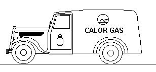
Fig : Calor Gas Dealers Van
Up to 1947 all distribution relied on rail transport, but following that hard winter Calor began using road haulage as well (although I am not sure why this was). In the 1960s the bulk gas rail tanks appeared, followed by the larger bogie tankers. As far as I know there were no calor gas liveried tank wagons, but I could be wrong on that point. Eventually the dealers set up larger storage and bottling plants and these were supplied by rail tank wagons either running onto private sidings or decanting into road wagons (this was NOT done at normal goods yards).
If your layout is based in the 1960's or later you might consider a simple transshipment point for LPG to feed road tankers (the first LPG tanks, similar to the Peco offering, appeared in 1962, see also 'Livery - Tank Wagons'). Facilities at a remote LPG depot can be quite small, perhaps only taking two, three or four of the Peco fifteen foot wheelbase tank wagons, a 'reach wagon' would be stored at the terminal used so the loco would not enter the loading area. Four Peco tanks occupy the same length as two Farish tank wagons (these latter have to be converted to LPG tankers, introduced in 967, see also 'Goods Rolling Stock Design - Rail Tanks').
There will be a concrete area with rails inset into it surrounded by a low wall to contain spillages, there should be a low gate to close off the entrance to this area and fitted with a sealing rubber strip along the bottom edge.
Small hydrants will be located alongside the track for coupling up the discharge pipes. If it is a busy terminal there might be some hoses left connected to the hydrants, these are grey or natural metal steel reinforced flexible hoses about a foot thick, the coiled metal guitar string 'D' is about right for this. These metal flexible hoses, called Anaconda Hoses, are expensive and most of the pipe-work would be solid metal tubing, either buried or carried above the ground on a steel framework.
The wagons might discharge only into road tankers, the lorry loading point would normally be a couple of hundred yards from the railway siding. The loading point will have a metal framework to support a set of water-spray pipes in case of a fire.
There was an article on such a small LPG terminal in Model Railway Constructor magazine, unfortunately I cannot confirm the date but I believe it was in the early 1980's. The rail tankers are available in 'N' from the Peco range and bogie LPG tankers can be produced from the Grafar 100 ton bogie tanker.
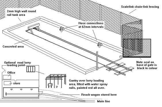
Fig : LPG Loading/Discharging point
Liquid Natural Gas
LNG is a very different animal, methane is the major component of natural gas, about 87% by volume, and this stuff only liquefies at -161 decrees C. or under very considerable pressure (about 60Kg per square cm if I remember correctly). This makes it exceptionally difficult to transport in road or rail tankers as a liquid as the pressure vessel has to be very heavy or the insulation very thick and the refrigeration plant required is much to big to be portable. The bulk LNG ships simply insulate their tanks and use the boil-off in their main engine. Naturally occurring LNG also contains significant quantities of ethane, propane, butane, and pentane (heavier hydrocarbons which are removed prior to its use as a consumer fuel) as well as carbon dioxide, nitrogen, helium and hydrogen sulfide. Having said which it is not toxic (unlike coal gas) and supplies are fairly plentiful at the moment. Compared to other hydrocarbon fuels burning methane produces only carbon dioxide and water and less CO2 than the other fuels.
UK imports of LNG began in 1964 with a shipment for Shell Oil from Algeria carried in the S.S. Methane Princess (LNG is only carried in purpose built ships) and more recently gas from the North Sea oil fields and since the early 21st Century it has been imported via pipelines from Europe and Russia.
LPG (butane and propane) has a higher calorific value than LNG so LPG can not simply be directly substituted for natural gas. However LPG can be mixed with air to produce a synthetic natural gas (SNG) that can be used with equipment designed for LNG.
Bitumen
Bitumen (or Asphalt if you are American) is the thick residue left after the more valuable fractions have been removed from petroleum oil. Technically the bitumen from a refinery is called 'residual bitumen' (to distinguish it from naturally occurring 'crude bitumen').This material can be used without further refining for waterproofing timber or 'tarred felt' roofing material. Mixed with stone chippings it is used to coat road surfaces, in the UK the tar coated chippings are known as 'asphalt' (see also Appendix One - Roads and road traffic - Roads and Road Works). The stuff used on roads was at least part processed, there were two distinct grades depending on whether it was to be mixed with chippings or sprayed onto the road surface as part of the final dressing. More recently it has also been processed to recover more of the lighter (still heavy) fractions, to be used as a fuel (for very big diesel engines). This mix is called HFO (Heavy Fuel Oil) and is very cheap but requires heating lines to be added to the fuel pipes, it is used in larger ships and also in some foreign power plants.
A pamphlet for Granton docks published in the early 1950s describes their bitumen facilities: <.p>
Many grades of Bitumen manufactured in Scotland are received at the installation in bulk road wagons or in steam heated rail cars, which are discharged into insulated storage tanks. The temperature in these tanks can be raised very quickly by means of a special process employing injection flame. Despatches from the installation are arranged by loading vehicles via insulated steam traced lines, thus enabling the product to be supplied at a suitable temperature to road making sites, etc.
The tanks used resemble those used in coal tar distilleries, although they tend to look a lot cleaner being either unpainted steel or clad in what looks very like concrete (they were insulated and the 'concrete' cladding might be some other material).
Bitumen will set solid at normal temperatures (it is supplied from heated tanks), so the bitumen feed lines were often fitted with steam 'trace pipes' to keep the stuff liquid. Making one of these mobile loaders would be rather more difficult in N as they were rather light and flimsy in appearance. The best bet would be to make the whole thing from wire and extend the vertical post down into the baseboard for support as shown in the drawing below.
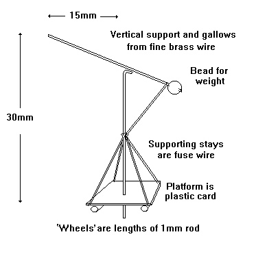
Fig : Top loading apparatus used for Bitumen
For more on the firms dealing in this product see 'Bitumen related firms' at the end of this section.
Petrochemicals
In 1920 Jersey Standard researchers produced rubbing alcohol, or isopropyl alcohol, the first commercial petrochemical, in the UK Shell set up a separate Petrochemicals Division in the 1920s. Petrochemicals have developed into a major aspect of oil industry, most modern plastics are made from petroleum based feed stock. Petrochemicals are also used in the manufacture of solvents and detergents and for making fibres such as nylon.
Commonly produced petrochemicals include a range of gasses which can be compressed to a liquid at reasonable temperatures: Ammonia, Butane, Butadiene, Ethane, Propane and Pentane are all routinely shipped as LPG in rail tank wagons. Genuine liquids include hydrogen peroxide, heptane, hexane and cyclohexane, used in the manufacture of paint and varnish removers and as feed stock for other chemicals (some of the English China Clay slurry tank wagons are actually redundant four wheeled cyclohexane tanks re-mounted on bogie chassis). Petroleum coke is a black granular form of carbon and shipped either in bulk or bagged, urea is shipped in bulk in the form of pellets (called 'prills') and quite large quantities of sulphur are recovered from some oils, shipped out in bags or drums.
Petrochemicals have proved a valuable resource for chemists and there have been some quite serious suggestions that oil should not be used as a fuel but should be conserved for use in making these chemicals. Current estimates are that we should run out of petroleum in about the year 2050, although the increasing costs of recovery will be passed on to the consumer and this should slow things down.
| ^ Go to top of page |
International Good Guys ~ Making the world a better place since 1971
All material Copyright © Mike Smith 2003 unless otherwise credited